Criteria to determine acceptable transducer
The RIWA Transducer is integrated within the welding electrode, where it transmits ultrasonic waves through the coolant and electrode cap into the welded material layers. To ensure proper weld inspection, the transducer's position, water path, and cap path, have to adhere to specific requirements. This document will run you through those criteria.
Transducer placement has to be coaxial to the electrode to guarantee signal propagation along the axis of the electrode-cap assembly. Provided:
- The transducer is not damaged
- The transducer is placed coaxially to the electrode
- The cap is placed coaxially to the electrode
- The cap has a smooth bottom with a radius of curvature in the range 22-65mm
Transducer assembly strength has to sit within the acceptable range described below:
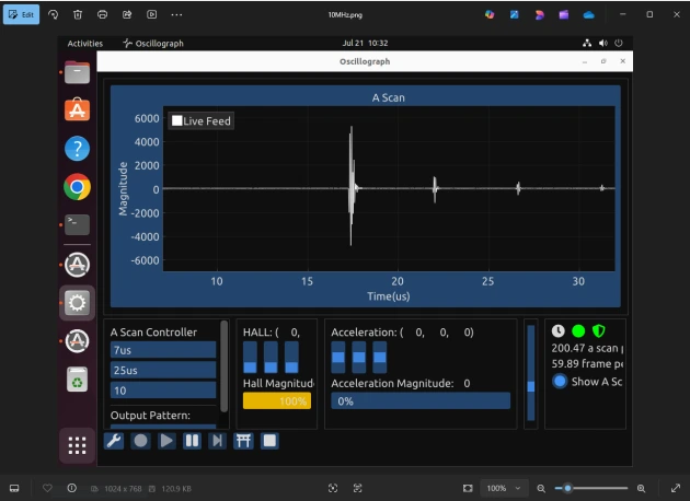
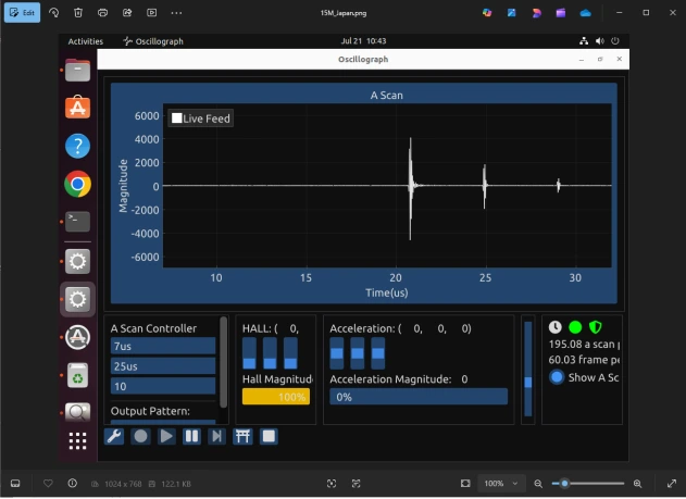
At 10 dB gain, the water-copper reflection must exceed 2000. Additionally, the second reflection must be at least 10% of the first reflection's value.
Below are examples of different arrangements which satisfy these criteria:
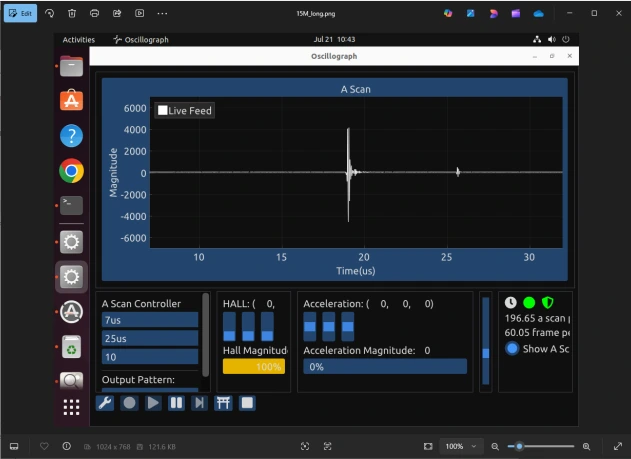
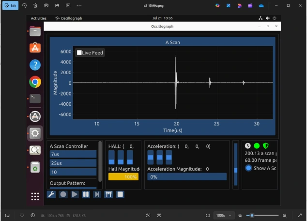
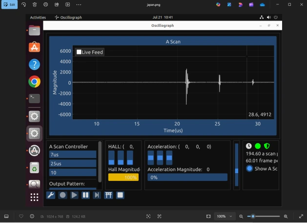
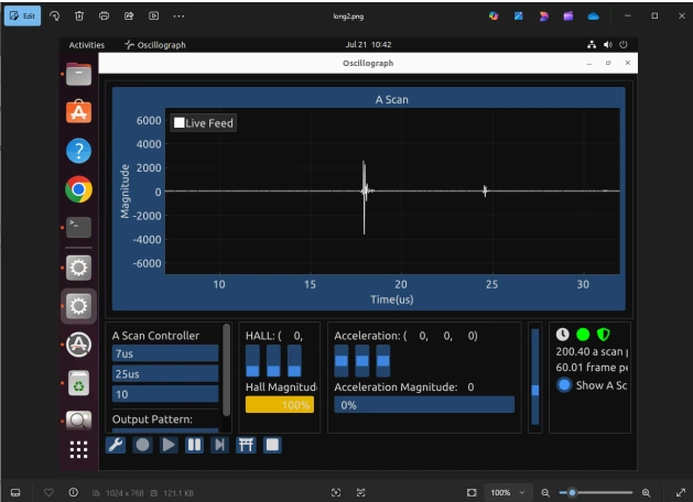
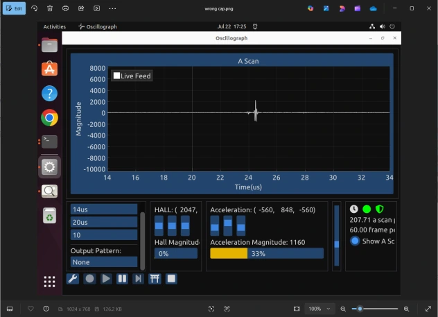
Below is an example of an unacceptable arrangement. The first reflection is below 2000, and the reason for this needs to be determined. A possible reason is:
- Damaged probe
- Misalignment of probe(non-coaxial)
- Cap misalignment or a mechanical deformation
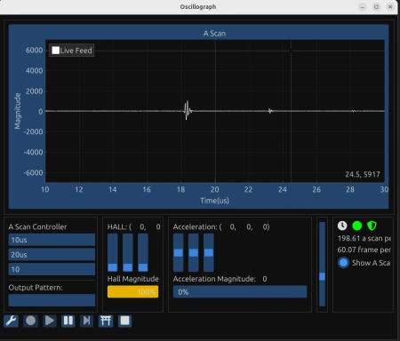
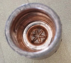
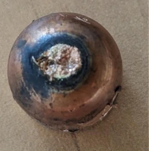
Here is an example of a burnt cap. A very small reflection, less than 10%.
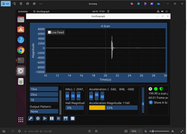
Here is an example of the wrong shape of the cap bottom. A low first reflection, split in two, and a non-visible second reflection.
