
RSWA User Guide

Common Software Features

This section describes features common to all software components.

On-Screen Keyboard

There are times during RSWA usage when you need to type text: entering passwords, file names, etc. Unfortunately, the RSWA unit does not have room for a built-in keyboard. Instead, when typing is necessary, you will see a virtual on-screen keyboard.

This keyboard allows typing using the touch screen.

Regular keyboard layout

note

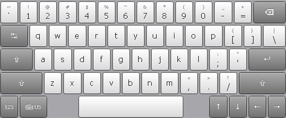
The layout of the keyboard depends on the currently active language.

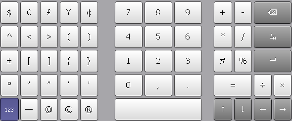
To switch to numeric keypad and back, use button:

This virtual keyboard is capable of supporting more than one keyboard layout in different languages. To manage keyboard layouts, go to Control Panel → Regional and Language Options → Languages.

Log In Prompt

When someone tries to run a protected Tessonics application they will get the log in prompt shown in Figure 1. Only the users who have permission to access to the protected application will be shown in the list. To log in, click your user name. If your user has a password assigned, then you will be prompted to enter the password.

Figure 1. Login prompt

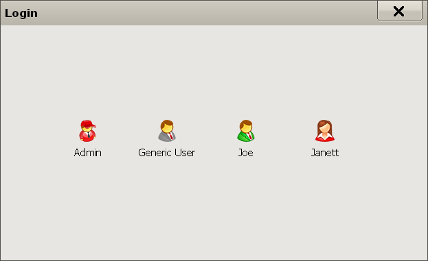
Each user has an associated icon to help them find their name when logging in. It's best practice to assign each user a different icon. See the "Managing Users" section in the "V3 RSWA Software Administrator Guide" manual for information on how to create and manage users.

Launcher

The Launcher allows the user to start Tessonics applications, and normally loads when the RSWA starts up and replaces the Windows desktop. The Launcher was designed and built for touchscreens, and is more convenient than a regular windows desktop. It also limits and controls user access to critical system settings and programs.

Main Window

Figure 2 shows the main Launcher screen. For each application that is available, a button is placed in the center (gray) section of the screen. Applications can be started by simply pushing the corresponding button.

Figure 2. Main Launcher window

Logging In and Out

Certain Windows and Tessonics applications have been protected and require users to have special privileges in order to use them. Some protected applications will allow you to log in (for that application only) when you try to start them and others will not start at all unless you are already logged in.

Clicking the Log In button, shown in Figure 3, will bring up the Login prompt discussed in Log In Prompt. When you log in this way your user information is retained, thus allowing you to start multiple protected applications without having to repeatedly log in. This is the recommended way to use the RSWA.

Figure 3. Logging in and out of Launcher

After you log in, the label on top of the button shows the name of the current user. The button caption changes to Log Out and now you can use it to log out of the system.

note

If the computer goes to standby while you are logged in, the system will automatically log you out to prevent unauthorized access by different users.

Turning Off

Clicking the Turn Off button will provide you with a list that allows you to Hibernate, Shut Down, or Restart the computer; see Figure 4. Shutdown puts the system into off mode, and Hibernate puts the system in Save-to-Disk mode. Restart simply reboots the system.

Figure 4. Turning system off

Switching Between Applications

When one or more applications are running the Switch button in Figure 5 becomes active. Clicking this button provides a list of all the running applications and allows you select which one you want to see or use. If an application is minimized this is the only way to bring it back into view.

Figure 5. Switching between applications

Accessing a USB Drive

You can use any standard USB drive to transfer files to and from the unit.

When a USB drive is plugged in, the button in Figure 6 becomes visible. Clicking this button provides the following options:

Figure 6. USB menu

Browse USB Drive - Opens Windows Explorer to work with files stored on the USB drive. This option is available only to users with Admin permissions.

Safely Remove USB Drive - Select this option before unplugging the USB drive from the USB port.

Software Updates - Selecting this option presents another list containing all the software that can be updated or installed from the USB drive. This option is only shown if there exists some updates on the USB drive. See the RSWA Administrator's Guide for more information.

warning

Always use the Safely Remove USB Drive option before unplugging the drive, especially if you've modified files on it. Otherwise you risk loosing your data.

Launcher Tabs

The Launcher Tabs, shown in Figure 7, determine what is shown in the center (gray) section of the Main Window, shown in Figure 2. The Applications, Utilities, and Admin tabs show different groups of applications that can be started by the user; the Admin tab is restricted to users with admin permissions. The Settings tab is also restricted to users with admin permissions and it is discussed below. The Info tab provides some information about the RSWA and contact information for Tessonics.

Figure 7. Launcher tabs

Settings Tab

The Settings Tab is available only to users with Admin permissions. It contains the following sections:

  • Control Panel
  • Launcher
  • Applications
  • Utilities
  • Admin
  • Deleted Items

Control Panel Section

Provides access to the standard Windows Control Panel.

Launcher Section

Allows you to choose which desktop application will be activated when Windows starts; the Windows Desktop or the RSWA Launcher. Unless you have a good reason for doing so, it is highly recommended that the RSWA Launcher be used. Using the Launcher limits a user’s access to the computer and helps prevent them from accidentally causing software problems. The Launcher Section also allows you to set the default language that is used with the Launcher and applications started from within the Launcher. The default language selected in this section is completely independent of the default language used by Windows and as a result will not have any affect if the Windows Desktop is used.

Figure 8. Launcher settings

Applications, Utilities, and Admin Sections

Allows you to add and remove programs from the Application, Utilities and Admin tabs in the main Launcher window. All three sections have similar appearance (see Figure 9).

Figure 9. Utilities settings

Push the Add... button to add a new item to the list. You will need to choose the name of the item, path of the executable file, command line options and an icon.

Push the Modify... button to rename an item, change it's icon or edit other options.

Push the Remove button to remove an item from the list. If you remove an item accidentally, you can restore it from the Deleted Items section.

Deleted Items

Allows restoring any programs that were deleted from the Applications, Utilities or Admin tabs.

Select a deleted item from the list and click Restore to move it back to one of the tabs, or click Purge to delete the item permanently.

Main Window and Terminology

The Main window consists of seven areas, which are explained in the following sections:

Figure 10. Main Array Explorer Window

  1. Button area
  2. Indicator
  3. C-scan area
  4. Inspection and information area
  5. Measurement history
  6. A-scan area
  7. Status bar

Terminology used in this chapter:

Inspection : A group of weld measurements that are saved together.

Part : A manufactured object that has spot-welds.

Inspection Order : The order in which spot-welds on a Part are to be measured.

Button Area

Setup : Setup the unit for measuring welds on a specific metal stack.

Get : Takes a single measurement. (Push and hold to enter continuous mode; see Continuous Mode Panel.)

The next three buttons are used with inspections. See the Inspections section for more details.

Pass : Clicking this button passes the current weld in the weld list. If a measurement hasn't been performed or the pass button is held down, a pop-up list of reasons for passing the weld will appear.

Fail : Clicking this button fails the current weld in the weld list. You must select a reason for failing a weld from the pop-up list that appears.

Next Unit (In Part Inspection mode) : Shown only for Part Inspections, this button replaces the New Weld button. Pressing it will start a new inspection using the same part you were working on.

New Weld (In Custom Inspection mode) : Shown only for a Custom Inspection, this button adds a weld to the list of measured welds.

The next two buttons allow starting, saving, and opening inspections. See the Inspections section for more details.

New Inspection/End Inspection : Starts new inspection. Once an inspection is started, this button changes to End Inspection.

Open Inspection : Opens a previously stored inspection (see Opening Inspections).

Settings : Allows changing various application settings (see Settings).

C-Scan Area

This area shows the image that is created from the collected measurement data. The green areas have fusion and the red areas do not have fusion.

Figure 11. C-scan area

Dotted Circle - Shows the automatic estimation of weld nugget location and diameter. If the estimation is off it can be manually adjusted by clicking the hand icon. Dragging the edge of the circle will resize it and dragging the interior of the circle will reposition it. The dots turn blue when in manual mode. Clicking the hand a second time will undo any manual modifications.

Small Background Squares - Represent the transducer's elements. The currently selected elements waveform will be shown in A-scan area (see A-Scan Area).

Spinning Wheel - Shows minimum/nominal size of the weld.

Indentation Button - Sets acceptable indentation range for the weld being measured.

Hand Button - Switches to manual circle sizing and back.

A-Scan Area

The A-Scan area shows waveforms (A-Scans) for the individual elements in the transducer's matrix.

Figure 12. A-scan area

You can choose which one out of the 52 matrix elements is displayed by making a selection in the C-scan area (see C-Scan Area).

White Curve - Shows the A-scan for the currently selected element.

Shadow in Background - Shows the composed A-scans from all the elements.

Number Boxes - Position of front-wall and back-wall reflections.

Green Vertical Lines - Gates showing the range for C-scan acquisition. These gates are set automatically when you press the Setup button. To adjust them manually, push and hold the touch screen inside the A-scan area.

Additional options are available through a drop down menu:

Figure 13. A-scan menu

Display Mode - Used to change how a-scans are displayed. The default value is Bipolar.

Ruler Units - Used to change the units used for the a-scan ruler. The default is Depth.

3T Mid. Thickness - Used to set the thickness of the middle plate when performing 3T inspections. Make sure this to off when performing a 2T inspection.

Processed A-Scans - Use this option to see a-scans with signal processing (default)

Raw A-Scans - Use this option to see a-scans without signal processing.

Indicator Area

Figure 14. Indicator area

The indicator area shows the estimations for the current weld nugget size and indentation. This area will also indicate errors involving the ultrasonic hardware. shows errors involving the ultrasonic hardware.

Measurement History Area

Figure 15. Measurement history area

This bar contains a history of all the measurements taken, stored in chronological order from the left. If you are not in an inspection it simply shows the history of the measurements taken. If you are in an inspection this bar contains all the measurements for a specific box in the Inspection Data section. Clicking on a measurement in the history bar will reload the measurement so it can be re-examined, and also change the measurement that is shown in the Inspection.

Status Bar

Figure 16. Status bar

Shows the currently logged in user, Inspection and Inspection Order that is being worked on.

Settings

This section discusses various settings of the Array Explorer application. Access to some settings is restricted depending on your permission level.

To access settings, click the Settings button in the button area.

Continuous Mode Panel

This setting determines the number of measurements taken in continuous mode. It can be set to take between 5 and 100 measurements (determines how long continuous mode lasts for).

To enter continuous mode, push and hold the Get button. To leave continuous mode, click the Get button again, or simply wait until RSWA cycles through the specified number of measurements.

Algorithm Panel

Algorithm panel is available only to users with the Advanced access level. It is here that you will be able to modify various algorithm settings, such as Absolute adjustment, Minimum size adjustment, Secondary Echo Processing, Peak Detector, Echo Shape Processing and Surface Follower.

Read this section to learn how these settings work.

Hardware Panel

Hardware panel is available only to users with the Advanced access level.

Disable controller - Allows to disable controller activation

Waveform Panel

Waveform panel is available only to users with the Admin access level.

Supersampling - The base sampling frequency is 66.6 MHz; supersampling is a multiplier that allows you to increase the sampling frequency (i.e. if supersampling is set to three the sampling frequency is tripled).

Averaging - This is a signal processing technique that reduces the amount of noise; multiple scans are taken and the average over the scans is used.

Inter-pass delay - Allows you to change the time delay between averaging scans.

Adjust Signal

Adjust Signal panel is available only to users with the Adjust Signal permission.

To aid in setting these parameters a grid of transducer elements and an A-scan window is shown. Clicking on a transducer element will cause the signal from that element to populate the A-scan window.

Delay - Controls the data acquisition delay. Then you change this parameter, the entire A-scan curve is shifted in the A-scan window. A properly calibrated tool must show the front surface reflection within the gates (green area in A-scan window).

Gain - Controls the amplitude of the signal. The signal should be adjusted so that the peaks are close to the horizontal lines connecting the gates (green area in A-scan window). For this adjustment, the transducer must be placed on a thick metal plate.

Auto Setup - Use Auto Setup to automatically initialize the Delay and Gain parameters

User Interface

These settings allow you to configure various user interface options.

C-Scan Area settings:

Display type - Allows you to choose between a smoothed color image and a gray-scale block image.

In-air indicator - Allows you to choose if you want to be warned when the transducer is not coupled to a sample and a measurement is taken.

Setup warnings - Warns the user if:

  • Setup button wasn't pressed before the Get button on a weld that has no recorded front plate thickness
  • Setup button acquires a front plate thickness that doesn't match the recorded front plate thickness (possibly checking the wrong weld)

The level of warning can be adjusted from none (Hide), to many warnings (Many). They correspond to how close the measured front plate thickness has to be to the recorded front plate thickness.

note

The Setup Warnings are only meant to help inspectors. They should not be relied upon.

Automatic decision - Controls the automatic decision mode. When automatic decision mode is activated, the obtained diamater and indentation are compared to the specified ranges (minimum nugget, minimum and maximum indentations) via the following procedure:

  1. The obtained diameter is compared against the minimum nugget diameter. If the obtained diameter is too small, then the decision algorithm determines that the weld is bad.

  2. If the obtained diameter is greater than the minimum nugget diameter and is also less than the target nugget diameter, then the decision algorithm determines that the weld is marginal. If the obtained diameter is greater than or equal to the target diameter, then the algorithm determines that the weld is good.

  3. Once a decision has been made based on the nugget diameter, the algorithm then checks the obtained indentation against the minimum and maximum indentation settings. If the obtained indentation is too small or too large, then the algorithm determines that the weld is bad, regardless of the decision it made based on the nugget diameter. If the indentation is within the minimum and maximum settings, then the previous decision made based on the nugget diameter is kept.

The automatic decision mode is only available when you run the software as Admin. The possible settings are:

  • Hide – do not show automatic decisions (default)
  • Show – show a quality decision suggestion, it is still up to the operator to make a final decision by pressing Pass or Fail buttons
  • Show and Apply – makes an automatic decision and automatically passes or fails the weld
note

In order to use automatic decisions, you must specify a nugget diameter for the weld.

Minimum diameter - This setting is only available when you run the software as Admin. In addition to the standard diameter reading, the software will also estimate a minimum diameter of the nugget. The minimum diameter reading is trying to stay more on the safe side of the diameter estimation. In the case of oval nuggets shapes, the estimated value will be closer to the minimum size of the nugget. In the example below, the standard diameter reading would be around (5.0 + 6.6) / 2 = 5.8mm and the minimum size would be 5.0mm.

Other settings:

Second interface - Controls the second interface indicator. When Position is chosen, the A-scan window shows the absolute position of the second interface. When Thickness is chosen, it shows the thickness of the stack measured through the center of the nugget.

Indentation indicator - Controls how the indentation is shown in the Indicator area (Indicator Area). When the Depth option is chosen the indentation is shown in millimeters. When Percent option is chosen, the indentation is shown as percentage (relative to the front plate thickness).

Use coin element G for AutoSetup - This option changes the message that is displayed during Auto Setup procedure. When set to 'No', a standard message is displayed that recommends to press transducer firmly against flat metallic surface. When set to Yes, a message then recommends to press transducer firmly against coupon G on the calibration coin.

Inspection and Information Area

When you are not in an Inspection this area provides some information about the RSWA and contact information for Tessonics.

Figure 17. Information and inspection data areas

When you are in one of the inspection modes this area provides additional options (see Inspections).

Inspections

An Inspection is a group of measurements (for example, all the welds inspected on one body part). Inspections allow the RSWA to organize and sort measurements for storage and future review, and eliminates the hassle of users saving measurements on their own. The Inspection area is only shown if you are currently in an Inspection.

There are two types of Inspections available to choose from: custom inspection and part inspection.

Custom Inspection Mode

The custom inspection type allows you to measure welds and assign names to these welds as you check them. A screenshot of a custom inspection can be seen in Figure 18.

Figure 18. Array Explorer in custom inspection mode

Weld name - Shows the welds name. The default names are numbered welds starting from one. Welds can be renamed individually by holding your finger on the weld until the pop-up menu appears (approximately 2 seconds) and then selecting Rename. There is also an advanced Auto-Generator feature, see Weld Name Auto-Generator for more information.

Measurement thumbnails - Each of these thumbnails represents a welds measurement. Clicking on a thumbnail brings the measurement back into the C-Scan for review, along with the history of measurements taken for that weld. This history list can be used to choose which measurement appears in the thumbnail; only the chosen measurement will be saved. There are two thumbnails because 3T stacks are supposed to be measured from both sides, and these measurements should be paired together.

Decisions - Each weld can have an associated pass or fail. Shown is either a check mark for pass, a cross for fail, or a dotted circle meaning no decision yet.

Reasons - Shows the reason chosen for failing a weld. Can also show the reason for passing a weld without measurement. During an inspection, the Pass, Fail, and Next Unit buttons appear enabled in the middle of the button bar.

The list of reasons for passing or failing a weld are programmed into the RSWA and cannot be changed by users. To change a welds pass or fail reason, simply hold your finger on the weld until a pop-up menu appears (for approximately 2 seconds) and select Clear Decision. You can now re-pass or re-fail the weld and select your new decision.

Starting New Custom Inspection

Custom Inspection can be started by clicking the New Inspection button in the top left corner of the screen. On the screen that pops up, choose Custom and press Next. You will be prompted to enter a name for the inspection. Entering a name is optional but doing so will make it easier to retrieve your inspection in the future. Now the New Inspection button changes to the End Inspection button.

note

If no parts have been defined yet, pressing New Inspection automatically chooses Custom and prompts for a name of the inspection.

Ending and Saving Custom Inspection

Clicking the End Inspection button or trying to close Array Explorer will ask you if you would like to save the inspection. If you choose to save the inspection, Array Explorer will do so without any further input from the user; i.e. you do not have to provide a filename or select a place to save the inspection.

note

Once an Inspection is saved, welds with decisions cannot be modified.

Renaming Welds

Push and hold a weld in the weld list. From the pop-up menu select Rename. Type in the new weld name, then push OK.

Weld Name Auto-Generator

If your weld names are similar, you can instruct the RSWA to name your welds for you using the weld name Auto-Generator.

Figure 19. Weld name Auto-Generator window

Push and hold a weld in the weld list. Choose Name Settings from the pop-up menu. Doing so will launch the window shown in figure 19. This window allows you to customize the prefix, postfix, number of digits, starting value, and increment. It also provides and example of what the resulting name will look like. To save the changes the user must click either the Save or Save and Apply button. Clicking save will apply the changes to all future welds; clicking Save and Apply will apply the changes to all existing and future welds.

Part Inspection Mode

The part inspection type is an advanced inspection type that uses coordinator defined factory information. All of the factory information is stored in a desktop PC and distributed to the RSWA. RSWA units then use this information to guide and organize an inspection, letting the inspector focus on inspecting welds. All of the factory data is created using the Template Designer application, and then imported into an RSWA via the RSWA Synchronizer program.

A screenshot of the information area in part inspection mode can be seen in figure 20.

Figure 20. Array Explorer in Part Inspection mode

Similar to a custom inspection, you can check welds and pass or fail them as you go along. Unlike a custom inspection, you follow a predetermined list of welds that an administrator has created for you. They are already named and ordered, and all that needs to be done is to inspect the welds.

List of Images

A part can have one or more images that show the part in different views. Front side, back side, etc. This list shows all the images that belong to the part being inspected. You can choose which image is shown by clicking on the image thumbnail.

Image Area

Shows the current image and the welds that are on it. The currently selected weld that is being measured is shown highlighted to help an Inspector find the weld to be measured. The buttons in the image area are explained in the following table:

ButtonDescription
Zoom in and out the image, centered on the currently selected weld
Toggle between showing all the welds or only the currently selected weld
Toggle between a regular size and full screen image display
Weld List

This part shows the list of welds that are to be measured for this part. An operator can check the welds in any order they like by selecting the weld they want to check from the list.

If the part has robot information, the list can be filtered to only show welds from specific robots by clicking and holding down on the weld list. See figure 21.

Figure 21.

Just like in a Custom Inspection, a Part Inspection allows using Pass/Fail buttons to pass or fail the current weld. Instead of a New Weld button however, a Next Unit button is provided. This lets you move to the next Inspection Order or repeat the same Inspection Order.

Starting New Part Inspection

In the main Array Explorer window, click the New Inspectionbutton button. In the window that pops up select Part and press Next. A list of parts that have been programmed into the RSWA is shown. Choose the part that you want and press Nxt. The next window asks you to name your Inspection, enter the part name (or leave it blank) and press Next. If there are any Inspection Orders defined for this part, a final window pops up showing a list of Inspection Orders to choose from. Select one and press Finish. The window closes and you can start checking welds.

note

If no Inspection Orders have been defined, the RSWA simply shows all welds on the selected part in alphabetical order.

Ending and Saving Part Inspection

Pressing the End Inspection button anytime during a Part Inspection will save your Inspection to the RSWA.

Opening Inspections

To open a saved inspection, click the Open Inspection button. This will launch the Open Inspection window shown in figure 22.

Figure 22. Open Inspection window

This window helps you find the desired inspection by providing filters and sorting options.

Inspection Types - Choose an inspection type to display, or select All to show all Inspection types.

Operator - Choose an operator's name to show inspections performed by the selected operator, or select All to show inspections from all operators.

Date Range - Choose either day, week or month. You will see the selection in the calendar change to reflect the chosen option.

Calendar - Click to select which dates are shown in the Inspection List.

The table on the right shows all the inspections that meet the above criteria. The table headers can be used to sort the table based on a given attribute.

When you locate the inspection, select it in the table, then click Open or Resume.

Open - Click the Open button to open the selected inspection in read-only mode for review.

Resume - Click the Resume button to open the selected inspection in resume inspection mode.

note

Previously measured welds cannot be modified in a resumed Inspection.

Upon saving, a resumed Inspection will update it's date and time to the new save time. This may mean that the inspection moves from an older date to a newer one. Also, a resumed inspection needs to be synchronized again with the Coordinator's PC if you want to see the newer data in the RSWA Reporter software.

By default, all inspections are stored in a database. This allows for fast storage, retrieval, and sorting of the measurements. Access to individual inspection files may be needed however, and the two following options allow exporting and importing inspections as files:

Export Inspection - Clicking this option allows you to save a copy of a single inspection into a file.

Open from File - Clicking this option allows you to load an inspection from a file into the RSWA for review.