RIWA-Obara Communication Protocol
This document describes the communication protocol between RIWA-RT and Obara Weld Controller
Communication between the RIWA software and the Obara software is based off the Data Exchange Protocol which includes commands and associated data.
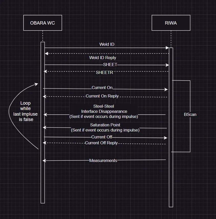
Weld Sequence Communication Diagram
All data are to be interpreted as unsigned integers unless otherwise specified.
The protocol specifies an 8 Byte packet for each command in the following format:
| Command | B0 | B1 | B2 | B3 | B4 | B5 | B6 | B7 | B8 |
|---|---|---|---|---|---|---|---|---|---|
| Command Code | Data (often FF) | Data | Data | Data | Data | Data | Data | Data | CRC8 |
- Command Code is one byte, with value starting from 210 (hex 2D) from WC to RIWA and with the value starting from 225 (hex E1) from RIWA to WC.
- Data is a 7 bytes field, where its value depends on the command.
- RIWA and WC use big-endian byte sequencing in the following order: big-to-small = from-left-to-right.
- RIWA does not support LSB/MSB byte sequential order.
- Check Sum is a CRC-8, defined as follows, and is sent as the last byte of the message (B8):
- Polynomial:
0x07 - Initial value:
0x00 - Direction: Counterclockwise
- Behaviour:
- If the RIWA system receives a message with a bad checksum, it replies with
ERR. - If the OWC receives a message with a bad checksum, it silently ignores it.
- If the RIWA system receives a message with a bad checksum, it replies with
- Polynomial:
Command Set: WC to RIWA
Some commands contain a time value. This value is NOT an absolute time, but the difference between two events. For example: command CON includes integer data value, which means difference between WID event and CON event in milliseconds.
| Command | B0 | B1 | B2 | B3 | B4 | B5 | B6 | B7 | B8 |
|---|---|---|---|---|---|---|---|---|---|
| WID | D2 | Penetration Threshold (%) | SSID sensitivity threshold (%) | 00 | Did-high | Did-low | wid high | wid low | CRC8 |
| CON | D3 | FF | 00 | Last Impulse 0/1 | Type of impulse: Preheat, main, temper | Impulse # 1,2,3,...n | CON1 | CON0 | CRC8 |
| COFF | D4 | FF | 00 | Last Impulse 0/1 | Type of impulse: Preheat, main, temper | Impulse # 1,2,3,...n | COFF1 | COFF0 | CRC8 |
| TD | D5 | FF | 00 | 00 | 00 | 00 | 00 | 00 | CRC8 |
| HLTH | D6 | FF | 00 | 00 | 00 | 00 | 00 | 00 | CRC8 |
| CHCAP | D7 | FF | 00 | 00 | 00 | 00 | 00 | 00 | CRC8 |
| SHEET | D8 | Number of Sheets | 1st TH high | 1st TH low | Middle TH high | Middle TH low | Last TH high | Last TH low | CRC8 |
Command and Data Description
WID, Data ID and Weld ID (Code) are structured as follows:
- Data ID: The data is a 2-byte integer, placed in B4 and B5. This is a unique identifier generated by the Weld Controller for each weld result. The Data ID serves as an additional unique identifier to distinguish weld results, especially in cases where multiple welds use the same schedule.
- Weld ID (Code): The data is a 2-byte integer, placed in B6 and B7. This represents the weld code value as it was assigned to the weld in the WC schedule.
- Bytes 1 and 2 (B1 and B2): These contain penetration and SSID threshold percentages, respectively, as signed integers [-128, 100].
These thresholds, along with the Weld ID and Data ID, should be sent to RIWA by the Weld Controller (HawkEye).
SSID and SP thresholds are a ratio on the range [-128,100] such that SSID threshold should always be less than SP threshold. They are the target ratio of nugget (liquid metal) penetration to the outer sheet. Suppose SSID threshold = 0 and SP threshold = 50; when the nugget appears in both the top and bottom sheet RIWA will send SSID event to OWC. This has indicated that the SSI has disappeared. So, we mean that 0% penetration into the outer sheet is equivalent to SSID; this is when the nugget just touches steel-steel interface between the sheets. When the nugget continues to grow further and has penetrated 50% of both the top and bottom sheets RIWA will send SP as the nugget has sufficiently penetrated the stack. These commands may be sent during each impulse.
The nugget has negatively penetrated a sheet if the nugget exists and has not crossed the steel-steel interface. i.e. if the top sheet is 1.2mm long and the top of the nugget lies 1.2mm below the steel-steel interface of the top sheet then we say the nugget has -100% penetration into the top sheet.
CON, Current ON event, data is 5 bytes between B3 and B7. B3 is a binary flag, set if there are no more impulses after the impulse has just begun. B4 is an enumeration for the impulse type, 0 if preheat, 1 if main, 2 if temper. B5 is a counter that indicates the number of times CON was sent for this weld. B6 and B7 are a 2-byte integer indicating the number of milliseconds since WID was sent by WC.
COFF is like CON.
TD (Tip Dressing event) has no data. Bytes 1 and 7 contain zeros.
HLTH Health Check has no data. Bytes 1 and 7 contain zeros. It is sent to RIWA to prompt a status report. It is recommended to send this command after weld controller restart, after power cycle, after part is done (by Robot/PLC), or whenever Robot/PLC decides it is proper time to check the status of weld controller and RIWA. HLTH is scheduled to be requested by OWC to RIWA approximately once every 1 to 5 seconds.
SHEET
- B1 Is a 1 byte integer ranging from 0-99 which indicates that number of sheets.
- B2-B3 is a 2-Byte integer ranging from [0,9999] representing the thickness of the sheet closest to the sensor in 100th of a mm.
- B4-B5 is similar but it is the sum of thicknesses of all the sheets in between the outer sheets.
- B6-B7 is the same as B2-B3 but for the sheet farthest from the sensor.
CHCAP
CHCAP has no data. Bytes 1 and 7 contain zeros. It is Check cap command from Weld Controller. Should be sent when electrodes are open and guaranteed to stay open for at least 500 ms (0.5 s). RIWA will inspect the ultrasonic signal which reflects from the cap and will analyze it. It will inspect reflection from internal bottom and external tip. It is recommended to send this command between parts (not between welds), and after cap change and after tip dress.
RIWA-OBARA Synchronization
| Command | B0 | B1 | B2 | B3 | B4 | B5 | B6 | B7 | B8 |
|---|---|---|---|---|---|---|---|---|---|
| WIDR | E1 | FF | 00 | 00 | 00 | 00 | 00 | 00 | CRC8 |
| CONR | E2 | FF | 00 | 00 | 00 | 00 | conl | con0 | CRC8 |
| COFFR | E3 | FF | 00 | 00 | 00 | 00 | coffl | coff0 | CRC8 |
| SSID | E6 | FF | 00 | 00 | 00 | 00 | ssid1 | ssid0 | CRC8 |
| SP | E8 | FF | 00 | 00 | 00 | 00 | spl | sp0 | CRC8 |
| ERR | EB | FF | data | data | data | data | data | errno | CRC8 |
| HLTHR | EC | FF | 00 | 00 | 00 | 00 | 00 | rprt0 | CRC8 |
| CHCAPR | ED | FF | 00 | 00 | 00 | 00 | 00 | chcaperr | CRC8 |
| SHEETR | EE | Number of Sheet | 1st th high | 1st th low | Middle th high | Middle th low | Last th high | Last th low | CRC8 |
| MEAS1 | E4 | FF | max-pene-top high | max-pene-top low | ta-ssid-bot high | ta-ssid-bot low | ta-ssid-top high | ta-ssid-top low | CRC8 |
| MEAS2 | E5 | FF | max-pene-bot high | max-pene-bot low | ta-sp-bot high | ta-sp-bot low | ta-sp-top high | ta-sp-top low | CRC8 |
The WIDR signal from RIWA to WC will be utilized to synchronize RIWA with OBARA WC. The Signal coming from WC to RIWA cannot be used because it undergoes latency time on the FTDI device. FT232 series has a timer that controls the data flow from the RS232 interface to USB which make this channel unpredictable since it depends on the time out of the timer.
The WIDR Signal will initiate a timer within RIWA and then trigger a timer on the WC side. These timers might be 0.3ms off due to the USB scheduling on the PC and data processing on the RS232 side of the FTDI chip. Based on document, this time mismatch is within the acceptable range of delay accepted for real time communication. All “time” values that need to be communicated in this system will use these 2 synchronized timers.
If time synchronization fails due to loss of WIDR data, the 6th and 7th bytes contain 0xFF.
(CON, COFF, SSID, SP)
Command Set: RIWA to WC
- MEAS1: Contains 3 parameters. Each is a 2-byte integer.
- B2-B3 ranging from [0,9999] contains the maximum achieved penetration into the sheet closest to the RIWA Sensor in 100th of mm.
- B4 and B5 are a 2-byte integer indicating the number of milliseconds that the sheet farthest from the sensor was penetrated beyond the SSID threshold.
- B6 and B7 are a 2-byte integer indicating the number of milliseconds that the sheet closest to the sensor was penetrated beyond the SSID threshold.
- MEAS2: Contains 3 parameters. Each is a 2-byte integer.
- B2-B3 ranging from [0,9999] contains the maximum achieved penetration into the sheet farthest from the RIWA Sensor in 100th of mm.
- B4 and B5 are a 2-byte integer indicating the number of milliseconds that the sheet farthest from the sensor was penetrated beyond the SP threshold.
- B6 and B7 are a 2-byte integer indicating the number of milliseconds that the sheet closest to the sensor was penetrated beyond the SP threshold.
- MEAS2 is sent immediately after MEAS1.
- SP (Sufficient Penetration event): Data is 2 bytes integer, placed into 6 to 7 bytes. Bytes 2 and 5 contain zeros. This value is the number of milliseconds between the most recent CONR and SP events. SP is sent to OWC when both the bottom sheet and the top sheet have been penetrated according to the SP threshold sent with WID.
- SSID: Like SP.
- ERR can be sent at any time to inform the WC that RIWA encountered an error. Error codes can be defined as needed.
errno= 0: no errors.- all data fields are 0
errno= 1: error.- all data fields are 0
errno= 2: bad checksum.- all data fields are 0
errno= 3: skip weld- B2 and B3 is the Weld ID and, B4 and B5 is the Data ID of the Weld being skipped (High byte first), the rest of data fields are 0's.
- HLTHR is sent as a reply to HLTH with status information contained within
rprt0, which should/needs to be defined to contain useful information.- healthy = 0b00000000,
- unhealthy = 0b00000001, generic error
- poor_signal = 0b00000010, gates failed
- no_pulse = 0b00000100, means RIWA did not receive a message within acceptable time range ,if
- this message is received this obviously means communication was re-established, this message is sent purely to indicate that connection was lost for a period of time.
- that OWC connection was lost briefly
- board_connection = 0b00001000, RIWA not connected to the ultrasonic board
- CHCAPR, response for CHCAP command.
chcaperr= 0: good cap.chcaperr= 1: first interface is bad (cap internal bottom is not acceptable).chcaperr= 2: second interface is bad (cap contact face is not acceptable).chcaperr= 3: both interfaces are not acceptable.
- SHEETR: Data is an echo of what was received in SHEET.
B-Scan Transmission
B-Scan Transmission will be sent by RIWA directly to HawkEye, not to the Weld Controller, using WSS (WebSocket Secure) protocol with TLS v1.3. RIWA will act as the WSS server. Certificates will be signed by Tessonics and provided to Obara. B-Scan will only be sent to clients who have a Tessonics-signed certificate with the common name "obara-hawkeye". Certificates must be stored in RAM as some type of buffer, not on the SSD.
Data will be sent over WSS in the following JSON format:
{
  "type": "b_scan", // indicates that the message contains B-Scan data
  "payload": {
    "data_id": "5678", // "data_id" corresponds to B4-B5 of the WID command and is a unique identifier generated by the OWC for each weld
    "weld_id": "1234", // "weld_id" corresponds to B6-B7 of the WID command and contains the weld ID as provided by the OWC in string format
    "b_scan": "<Base64 encoded image data>" // we will send a jpg in string Base64 format
  }
}