Panel I/O Breakdown
I.O: All I.O on the RIWA Panel can be seen in the picture below.
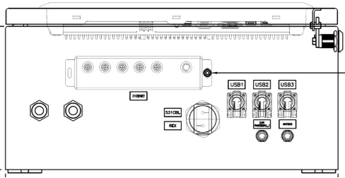
- USB: All USB ports seen in the picture above are USB 2.0 standard and have a 480Mps Transfer rate.
- A-Code Ports: There are 2 M12-A coded I.O ports.
- PLC port: The port tagged Anybus in the picture above, refers to the port for the 4-pin A coded M12-A coded cable to communicate with the PLC.
- LAN Passthrough: The port tagged LAN
Passthrough_1on the picture above refers to the 4-pin M12-A coded connector for the ethernet LAN connection. This is required for remote calibrations, servicing and maintenance.
- X code Panel to switch cables: There are 2 switch cables that need to be connected. They can be seen in the picture above under the following tags.
- 531CBL: This will be a 5 pin A code M12 cable protruding from a grommet denoted on the picture above as a large hexagon. This cable is to be connected to the switch power port. The ports of the switch can be seen in the picture below.
- Remote Module: This cable will also protrude from the hexagonal grommet on the picture above. However, this one will be 8 pin X coded cable. This cable will go to the Remote module port marked on the picture below.
- Wire Glands: on the left most side in the picture above, two identical hexagons with circles can be seen. These two hexagons poon the diagram represent two wire glands in the same position as the real Panel. These wire glands are a method to introduce cables into the Panel while sealing them.
- Use of Grommets: One will be used for the PSU cables. The other is available for any extra peripherals.
- Sealing Grommets: When a wire passes through this gland. The assembler needs to ensure they tighten the nut on the grommet. This will seal the Panel from dust and debris.
- Grommet Precautions: If no wire passes through one of the grommets, the grommet not used needs to be tightened, this will seal the internals of the Panel off from the external environment.
