Catalogue
Overview
The Catalogue menu allows you to manage your part groups. From here, you can search for existing part groups, add new ones, edit current ones, and delete part groups.

Part Group Management
General Settings
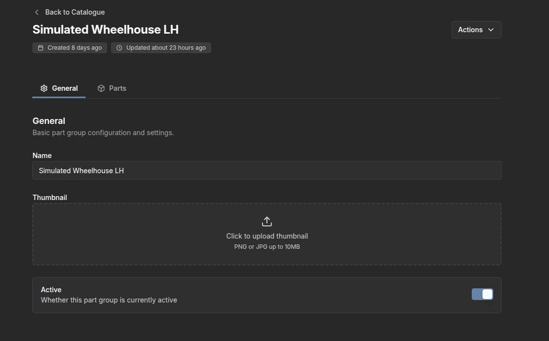
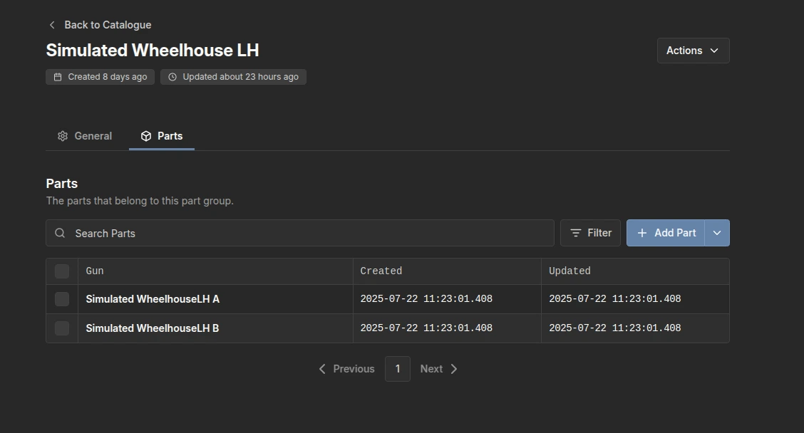
Within a part group, you can customize sit. This includes giving it a name, adding a thumbnail image, and toggling a button to indicate if the part is currently active. You can also add individual parts associated with that piece of equipment. For example, in this instance, a left-hand wheel housing will have Part A and Part B added as its two distinct pieces.
Parts
Similarly, you can perform the same actions within the Parts section, which contains data such as the welding gun, its creation time, and last updated time, maintaining the same layout as the Catalogue homepage.
Configuring a Part Group
General
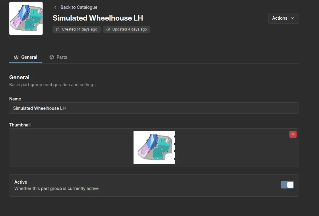
When editing your part groups, two setting will appear: a General setting and a Parts setting. The General setting contains basic part group configurations and settings.
Parts
Inside the Parts settings, you will see the parts associated with that part group. You can add a new part or click on an existing part to configure it.
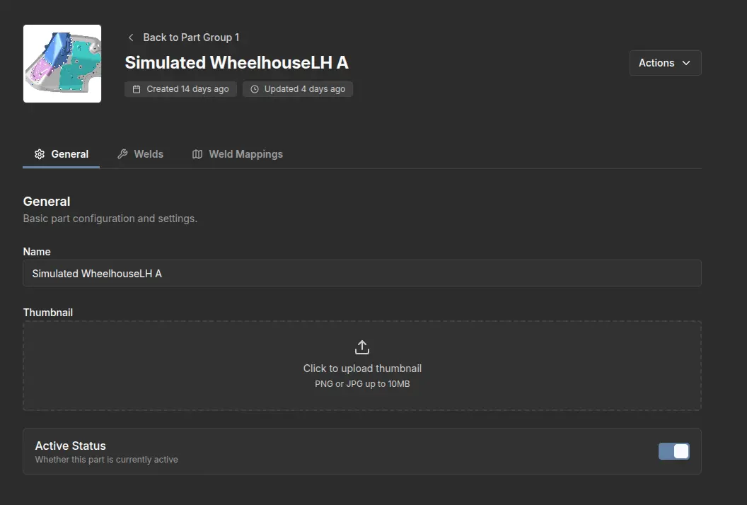
Configuring an Individual Part
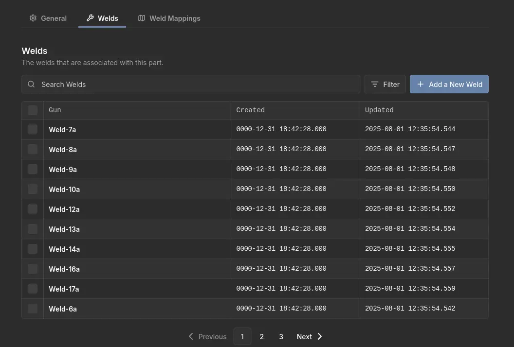
Welds
Inside the Welds settings, you can view all the welds associated with that part. You can also add a new weld part.
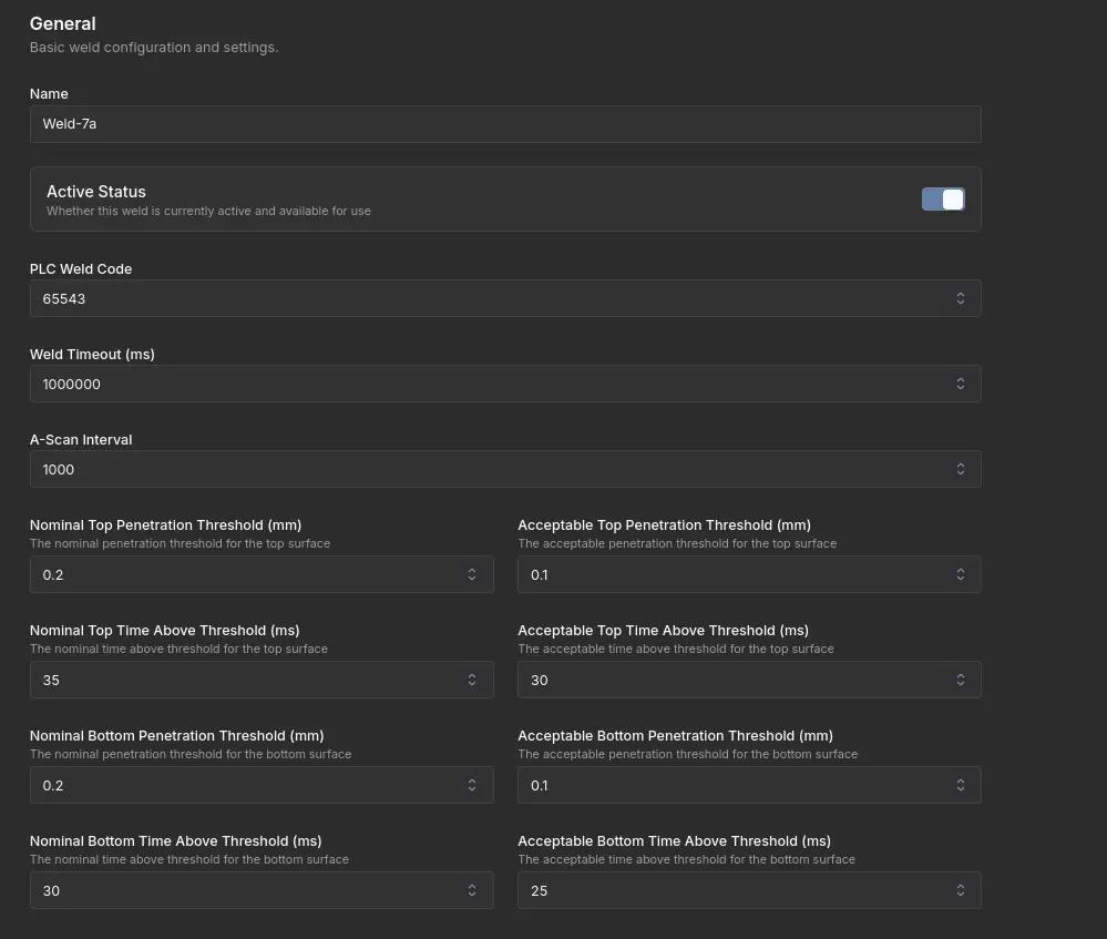
General Weld Configuration
When inside the General settings, you have access to basic weld configuration options.
Gun Configuration
When inside the Gun settings, you can configure the gun associated with that part.
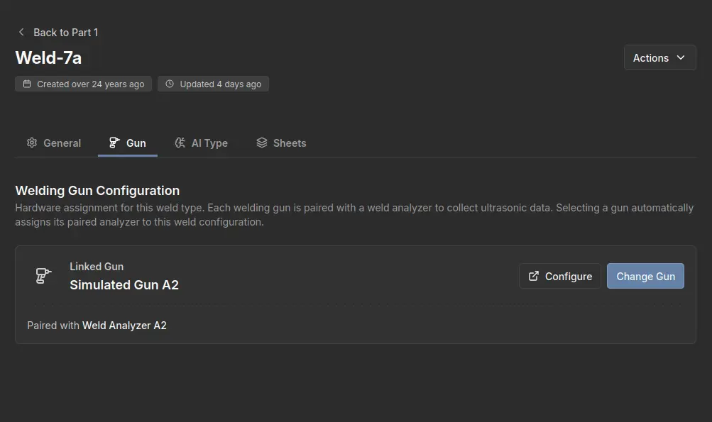
You can either configure the existing gun or change it to a different one.
AI Type Configuration
When inside the AI Type settings, you can configure or change the AI type.
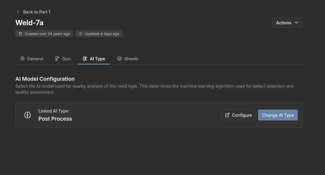
When changing the AI type, you have the option to choose between Post Process or Real Time.
Sheets Configuration
When inside the Sheets settings, you can configure and manage your current sheets.
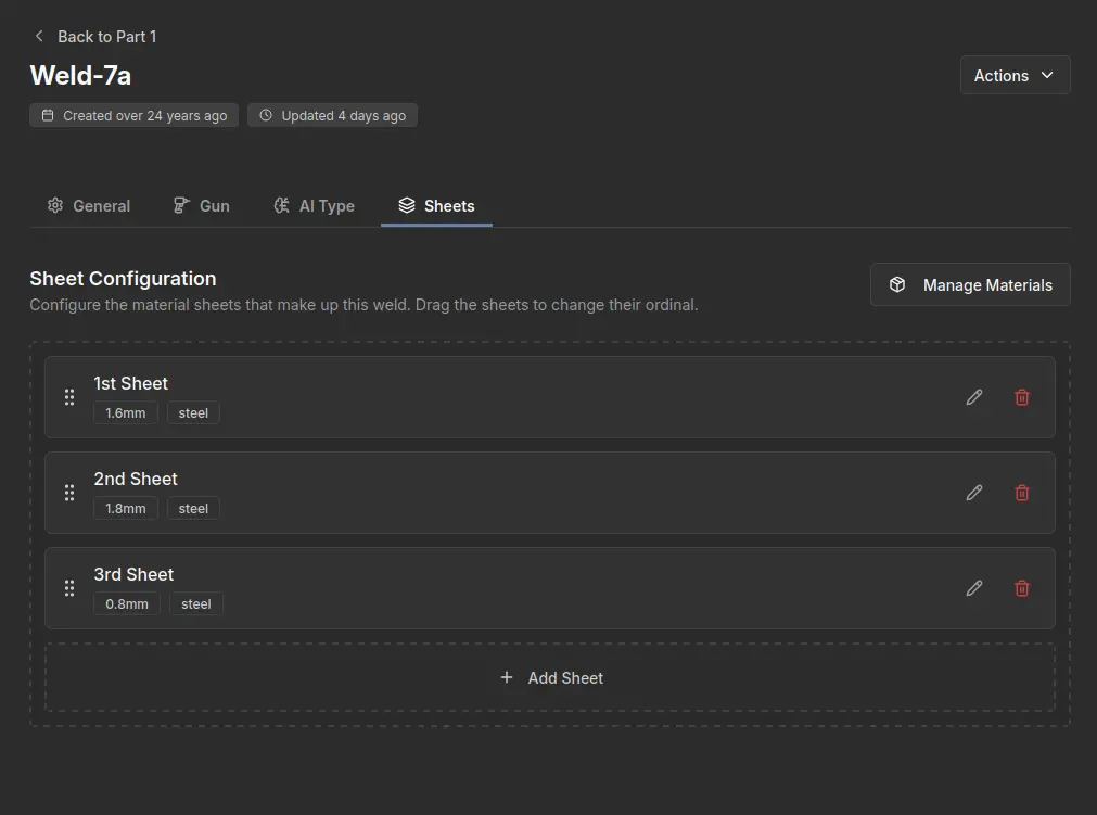
Inside Manage Materials, you can view and manage your sheets. When creating a new material, you are required to enter the material name and sound speed.
Inside Add Sheet, you can now select a material based on the materials you have currently configured and then select a thickness.
Weld Mappings
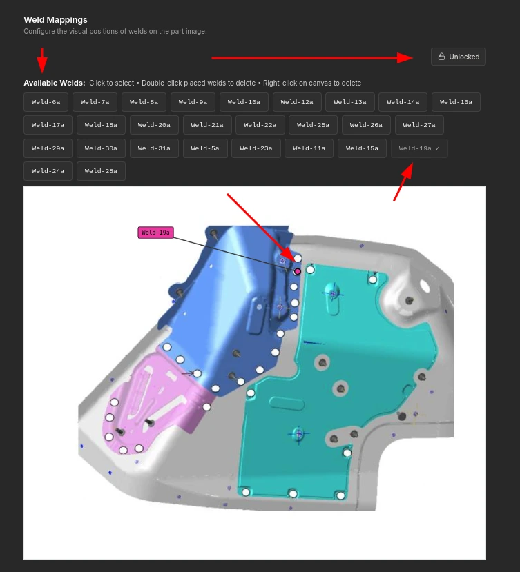
When inside Weld Mappings, you can configure the visual positions of the welds on a part image. To move the welds to their respective positions, you must click the Locked button to enable configuration.
Once the canvas is unlocked, you can click on a weld from the list of available welds and place it in its respective position on the image. Additionally, if you want to delete a weld from the canvas, simply double-click on the weld you wish to remove from the Available Welds list.
