Probe Configuration
Configure your ultrasonic probe. This page allows you to adjust settings related to your ultrasonic probe.
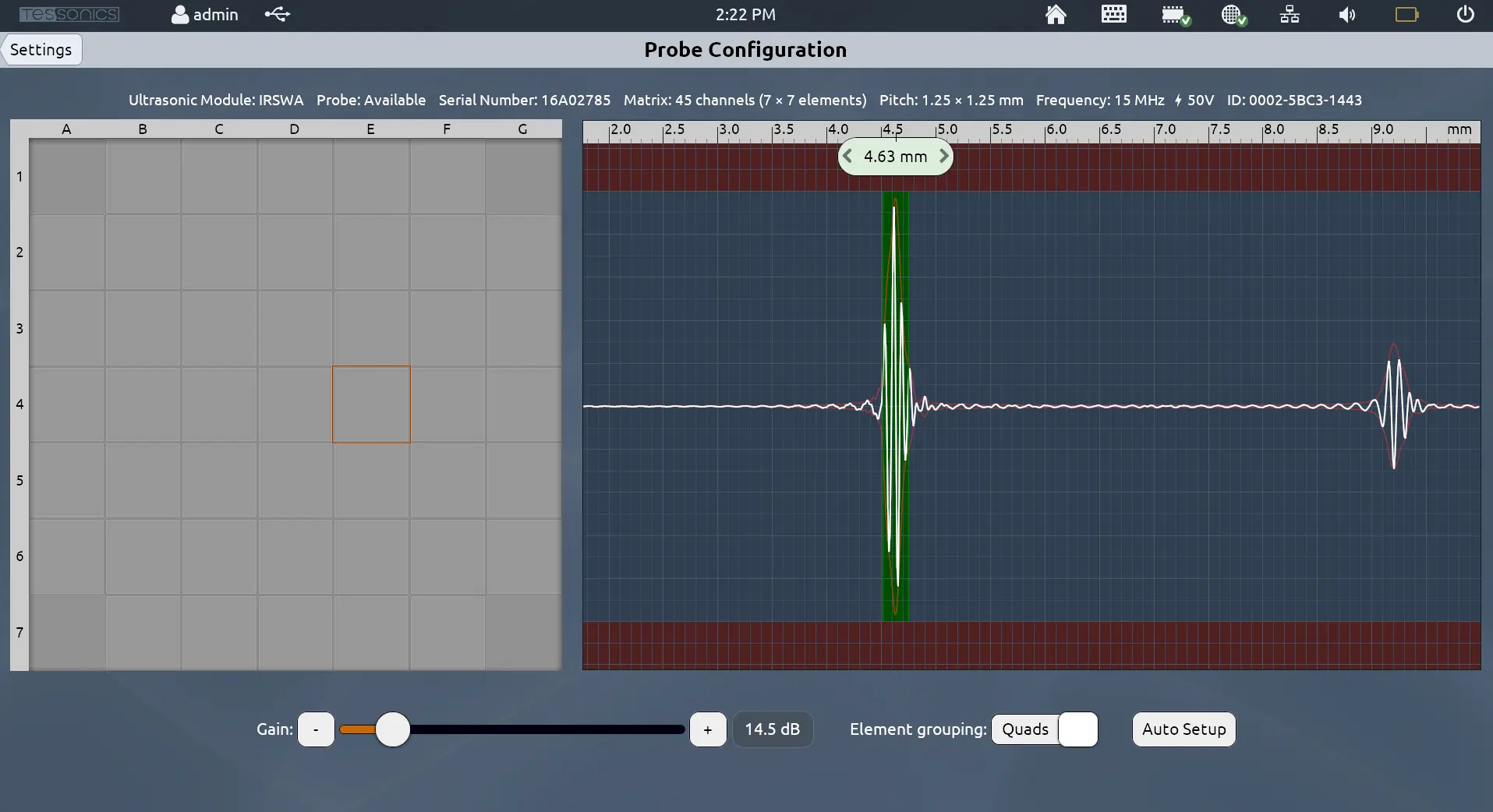
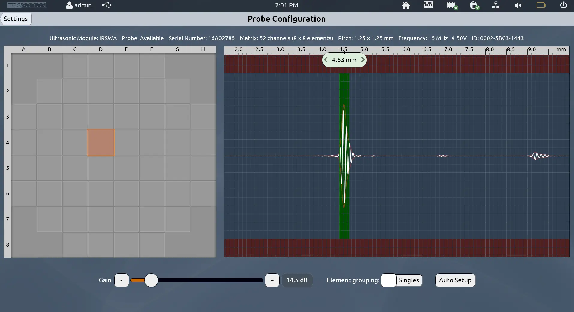
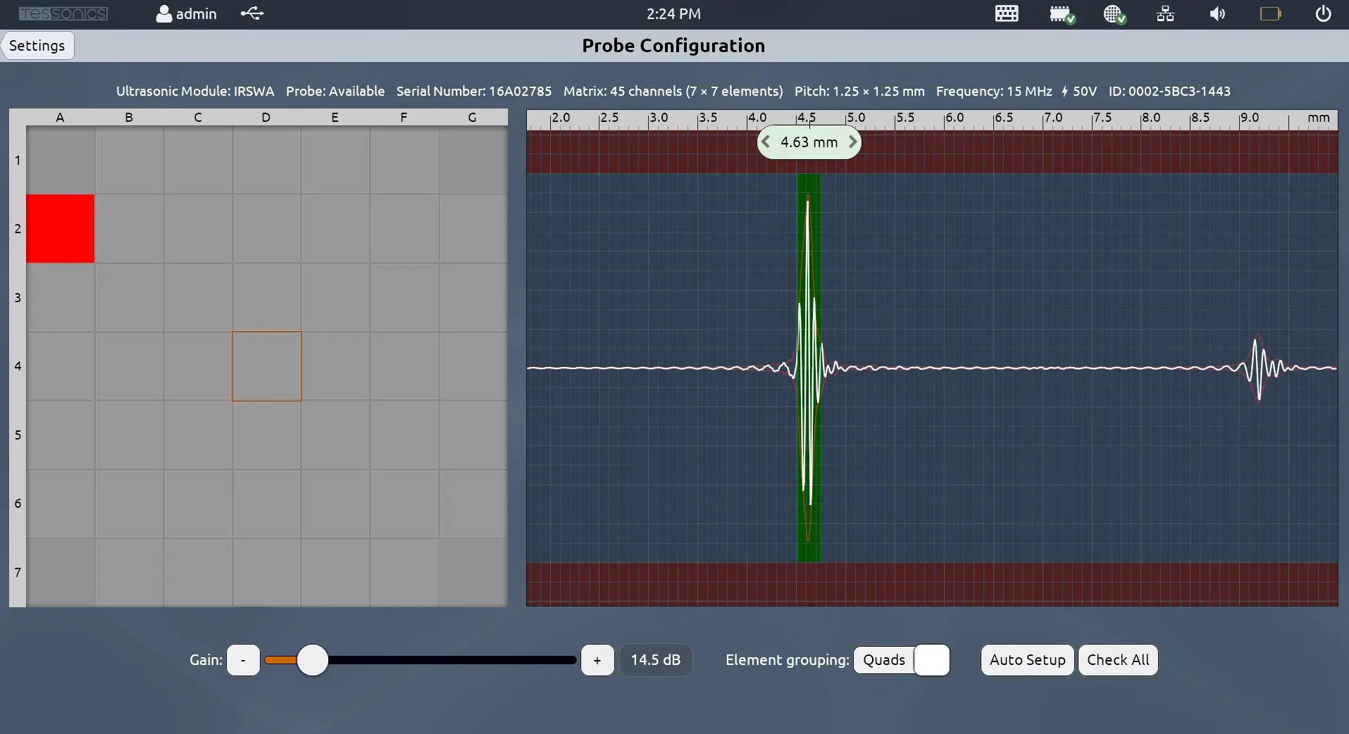
The grid on the left panel shows the elements of the probe in the same way they appear when performing inspections. The right panel shows the live A-Scan readings from the selected element.
Auto Setup
Auto Setup automatically determines the proper settings, including the gain and offset, for the ultrasonic probe to read the most accurate measurements.
Follow these steps to ensure the best quality:
- Make sure the probe's delay line is flat and in good condition.
- Ensure there is no gel on the surface of the delay line.
- Ensure the probe is facing the open air.
In most cases, the Auto Setup action should be sufficient for operating your RSWA.
Whenever changing the delay line, it is recommended to perform another Auto Setup.
Weak and Problematic Elements v4.9.1
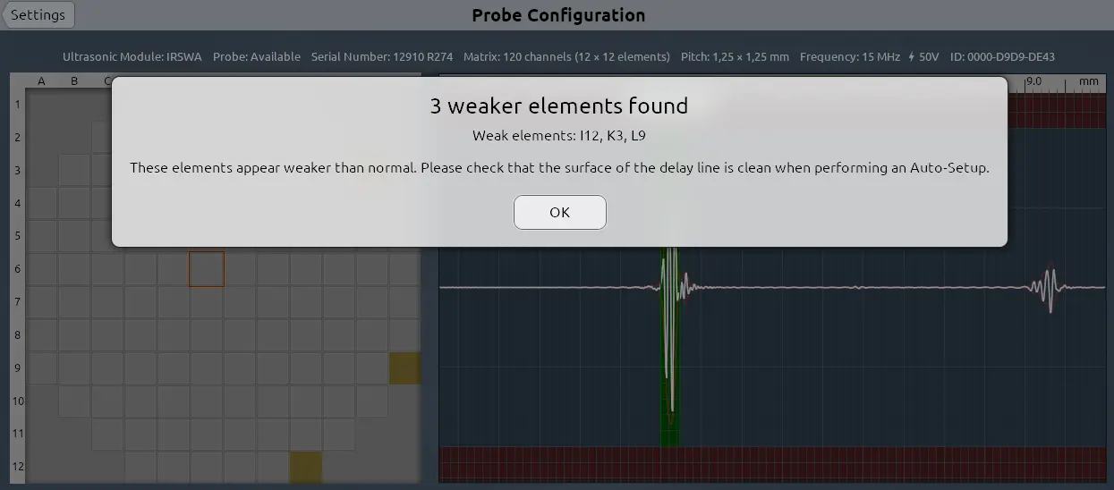
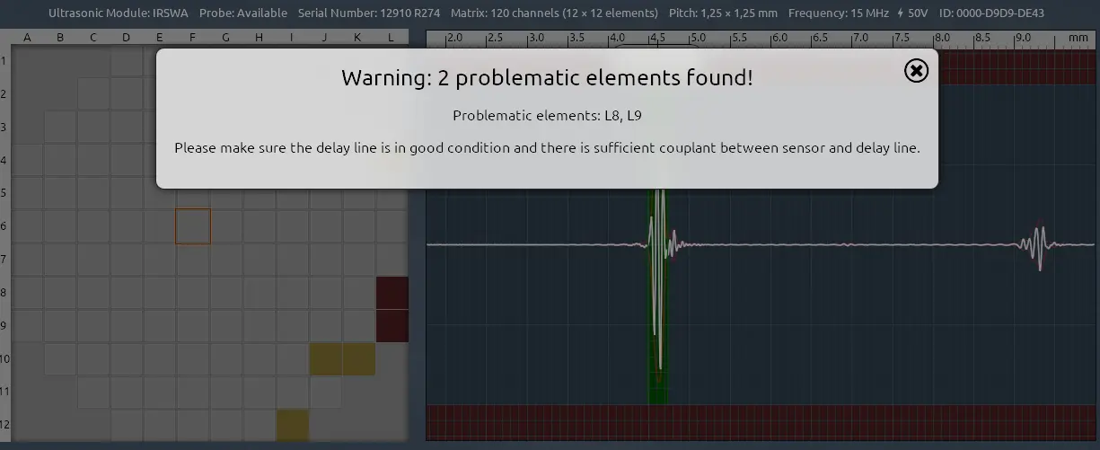
After performing an Auto Setup operation, if there are weak or problematic elements, the software will alert the user.
Elements whose signal is less than 5% of the normal range are considered weak elements. These elements are likely weak because there is leftover gel on the surface of the delay line. Cleaning the surface of the delay line and performing an additional Auto Setup operation should resolve this the majority of the time.
Elements whose signal is less than 1% of the normal range are considered problematic elements. These could be elements that were damaged or are non-operational.
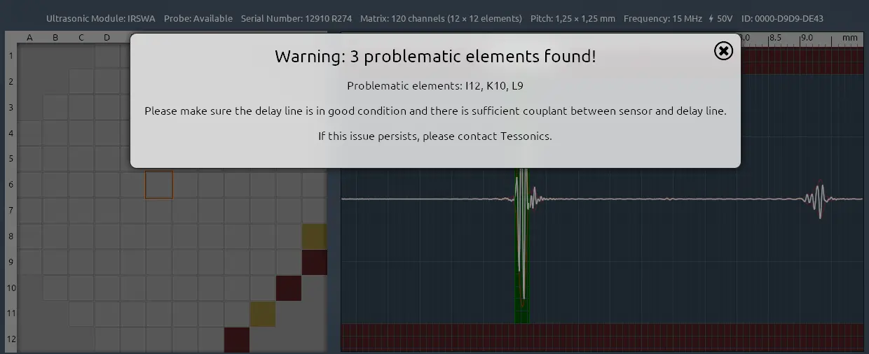
While it is possible to retrieve accurate readings with 1 or 2 problematic elements, accuracy can no longer be guaranteed if there are 3 or more problematic elements. In this case, contact Tessonics for guidance on how to move forward.
- Weak Elements
- Problematic Elements
- 3 Or More Problematic Elements
- Outdated Display for v4.7.0
For version 4.7.0, elements whose signal is less than 10% of the normal range were highlighted in bright red. This was enhanced in later versions for improved clarity, as this could lead to false-negatives.
Gain
The "Gain" slider boosts the signal retrieved from the probe by a certain number of decibels.
While Auto Setup should determine the appropriate gain level, it can be manually adjusted to values between 10.0 dB and 48.0 dB.
Offset
Within the A-Scan panel, there is likely a green box surrounding the first peak with a marker (the screenshots above show 4.63 mm). This refers to the offset required by the thickness of the delay line when performing A-Scan measurements.
While this can be modified by dragging left or right, there is rarely a reason to modify it manually. The Auto Setup operation should automatically determine the appropriate offset.
Element Grouping
Array Explorer supports two grouping patterns:
- Singles: This is the default grouping. Each element on the C-Scan panel corresponds to each element on the probe itself.
- Quads: Each element on the C-Scan panel corresponds to the average of a 2x2 grid of elements on the probe, which makes the C-Scan grid appear smaller with less elements. This can be useful when there are issues with some of the elements.
- Single Element Grouping
- Quad Element Grouping