Managing Part Images
Each part can be associated with images and hot spots for welds. Using part images is not required, but it provides a convenient guidance for the operator.
To switch main view to an image display, select a part in the navigation tree, then click Welds in the main area, or expand a part node in navigation tree, then select the Images node.

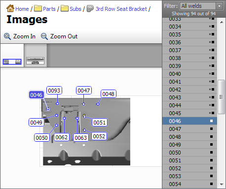
At the top of the view, below the toolbar there is a list of all images associated with the part. On the right hand side, there is a list of welds with filters. The rest of the area shows an image with hot spots.
Adding New Images
To add a new image, click Edit → Add Image in the main menu, or right click in the image list area and choose Add Image from the popup menu. In the Add Image dialog, choose whether the new image will be opened from a file or will be based on one of the images that are already in the database, then click Next. If the file option was chosen, choose the file to use then click Open.
The next page in the Prepare Image dialog allows to crop the image, flip it and rotate it. When done, click Next.
The last page in the Prepare Image dialog allows to adjust resolution and compression format for the image. Adjust the necessary parameters, then click Ok to complete image import.
Adding Welds
When a weld is placed on an image, that is referred to as a hot spot.
After the new image is imported, you can drag and drop welds from the list on the right onto the image. The same weld can appear on more than one image. For convenience, the list of the right can be filtered as one of the following options:
- Show all welds;
- Welds that belong to current image;
- Welds that do not belong to current image; and
- Welds that do not belong to any image.
When the part contains only one image, each entry in the weld list has a small icon on the right to indicate whether the weld is already inserted somewhere in the image (solid square) or not (small hollow square). If the part contains more than one image, there is an additional icon that indicates whether the weld belongs to any other image in this part.
To adjust hot spot placement, you can click and drag its target point or the label. To select more than one hot spot, hold the Ctrl key on the keyboard and then click on hot spots.
Alternatively, hold the Ctrl key down, then click outside the hot spot and drag the selection rectangle. Selections in the image and in the weld list are automatically synchronized.
The image view will automatically try to arrange labels to minimize overlapping between them. If the labels still overlap due to high density, you can zoom image in and out. To control image zoom, use View from the main menu, image popup menu or a mouse wheel.
Removing Hotspots
To remove a hot spot from the image, select it, then hit Delete key on your keyboard or choose Edit → Remove Hot Spot (or Edit → Remove Selected Spots for multiple selection) from the main menu or from the image popup menu.
Quick Collection
Welds that belong to quick collection will have the star symbol next to them. You can use the popup menu or Edit option in the main menu to manage quick collection membership for selected welds.
Return to Weld View
It is also possible to jump to the weld view to see or modify specific weld properties. Select welds that you want to manage, then click Edit → Edit Weld details from main menu or from popup menu to switch back to weld properties view. The welds that you had selected in the image view will be automatically selected in the weld properties view.