Image Panel
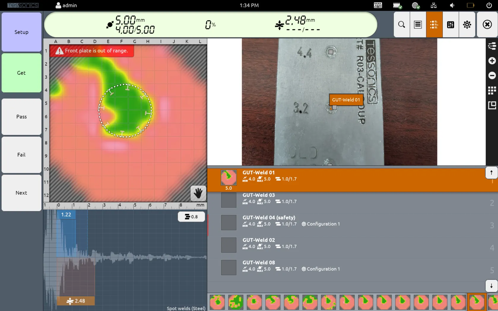
The default display is the joint list, which can be toggled by selecting the third top button. This contains an image of the part along with a list of each joint.
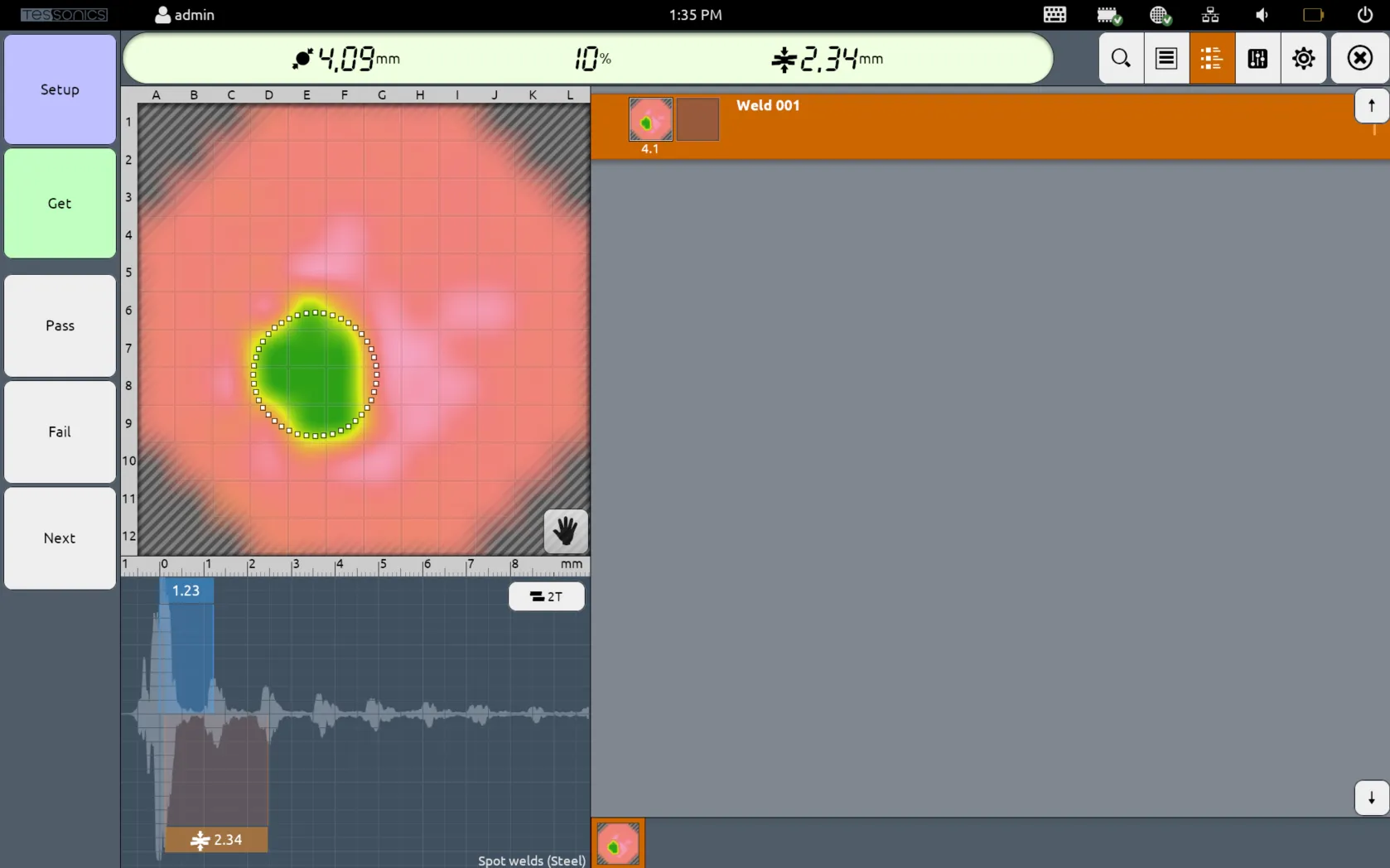
For Free Mode Inspections, since there is no part associated with the inspection, only the joint list is displayed.
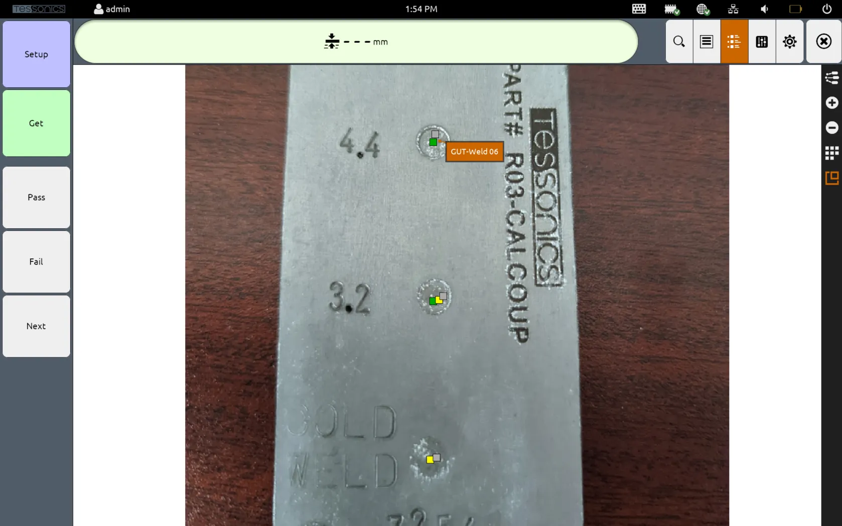
The image display shows the image of a part, along with the labels and locations of the various joints on the image (as configured in Desktop Tools). When each joint is selected, the image automatically scrolls to the location of the given display.
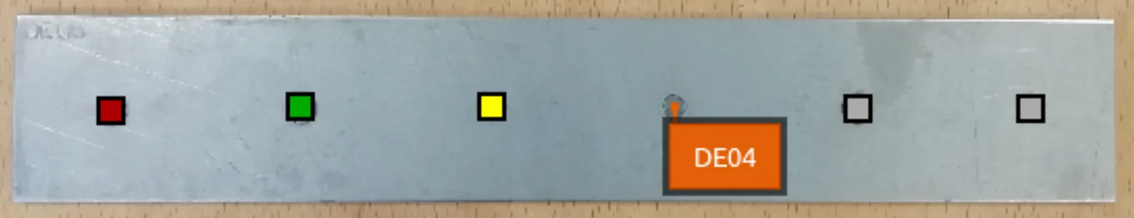
Each joint on the image is colored using either a square or an X. The black X represents joints that belong to the image but are not present in the current inspection route.
These X joints can be hidden via the Hotspot Label Visibility setting.
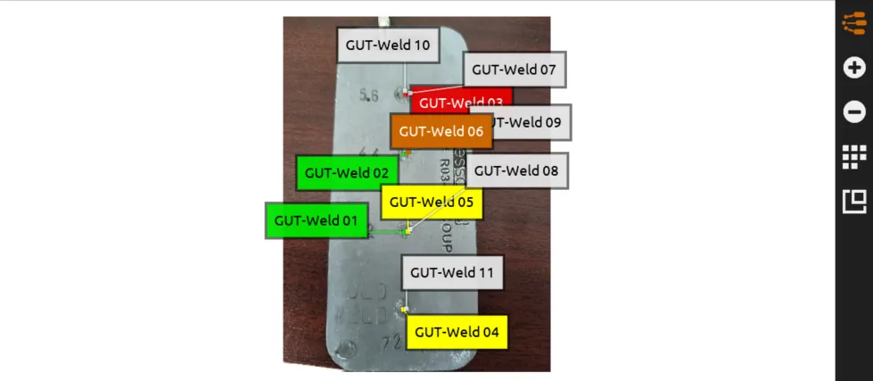
All joints within the current route are displayed with a small square. The color is determined by the following:
- The green squares are joints that were passed.
- The red squares are joints that were failed.
- The yellow squares are joints that were skipped and were neither passed or failed. In the screenshot below,
GUT-Weld 04andGUT-Weld 05were skipped with no decision being assigned. - The grey squares are joints that are next in the list that have not been inspected yet.
There are also five side buttons which have their own functions.
Display All Labels
The top button toggles the display of all labels of all joints in the image. The color of each label is determined by the same criteria above, plus two more conditions:
- The orange label is the selected joint, or the joint that is actively being inspected.
- The white labels are joints that are next in the list that have not been inspected yet.
- The grey labels are joints that belong in the part's image but not in the current route. These joints themselves are drawn with an X.
Zooming In and Out
The + and - buttons control zooming in and out of the image. As you zoom out, the labels might shuffle to avoid colliding with each other.
Switch Image
The grid button allows you to select which image to view. Depending on your specifications, it may be required for a part to show different perspectives using multiple images.

Toggle Full Screen
The last button makes the image display across the entire F2 screen, overtaking the C-Scan panel, A-Scan panel, joint and measurement lists.