Joint List
Along with the Image Panel is the Joint List, or the list containing all the joints of the inspection route for the current inspection. This list may display different information depending on the type of inspection.
Free Mode Inspection
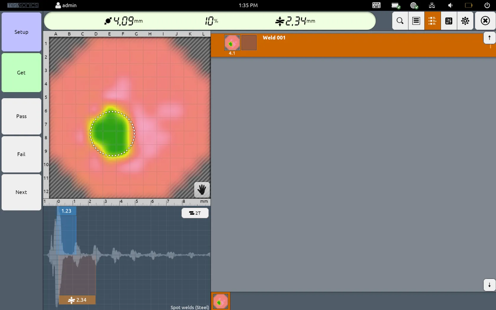
For Free Mode Inspections, since there is no template data for the given inspection, the joint list merely contains the list of all measured joints with their measured C-Scans. Each joint is automatically created by selecting the Next side button, and contains two slots by default (more info here).
By pressing and holding a given joint, you can select Delete to delete the selected joint. You may also select Properties to modify the joint name, custom notes and the decision (pass, fail or unknown).
Template Mode Inspection
For Template Mode and Restricted Mode Inspections, the joint list also contains additional template data for each joint, as configured in Desktop Tools. This contains the following information:
- The joint name;
- The category name in brackets;
- The category color on the leftmost side (i.e. red in the provided screenshot below);
- The minimum and target diameter values;
- The stack thickness values (i.e.
front plate/middle plate/back plate); - The measured C-Scans;
- The measured diameter value (displayed underneat the C-Scan);
- The decision (green checkmark for pass and red X for fail);
- The decision reason (if applicable);
- The algorithm preset name; and
- The robot name and schedule (if applicable).
- 4.9.0 and Newer
- 4.8.0 and Older
For software versions 4.9.0 and newer, the joint display will be different. It will now render the measured diameter, indentation and stack thickness for each measurement if these calculations are available.
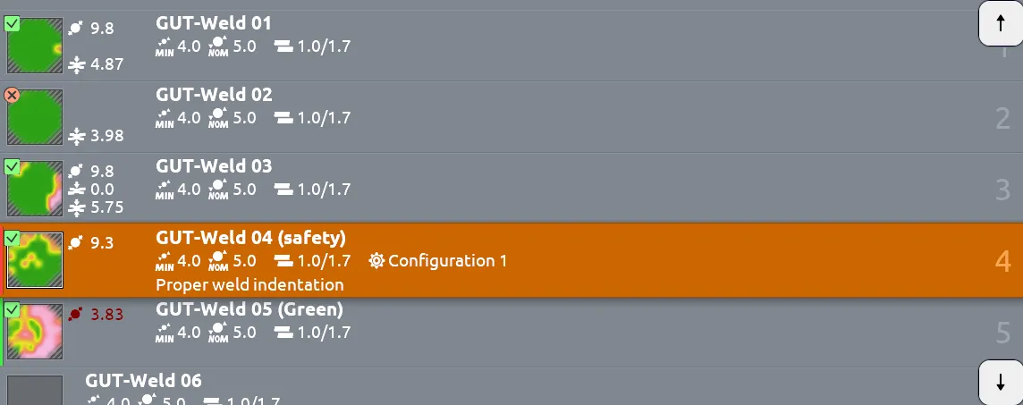
Additionally, any measurements out of bounds (as per the template specifications defined in Desktop Tools) will be colored red. In the sample screenshot below, the measured indentation and stack thicknesses are out of bounds, while the measured diameter is not.

By pressing and holding a given joint, you can select Properties to add custom notes or change the decision.

Stack Changes
When the stack thicknesses change, according to the template data, a marker ! Stack Change is displayed. Selecting this marker displays how the stack values are changed. If a plate value has a question mark (?), that means the plate thickness was not set in Desktop Tools.
Whenever the stack thicknesses change, the inspector should carry out a new Setup operation. More information is provided in the Best Practices section.

Different Views
When modifying the display settings, you can change the display of the joint list.
List View
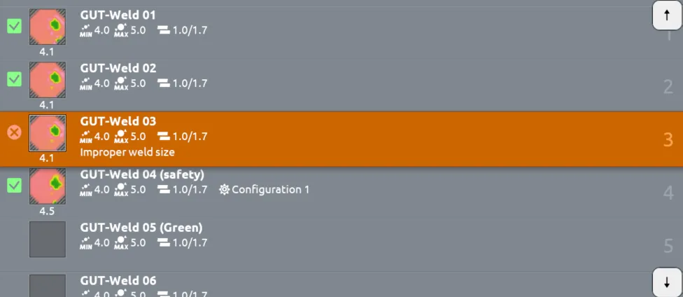
The default view is List, which displays all the details mentioned above.
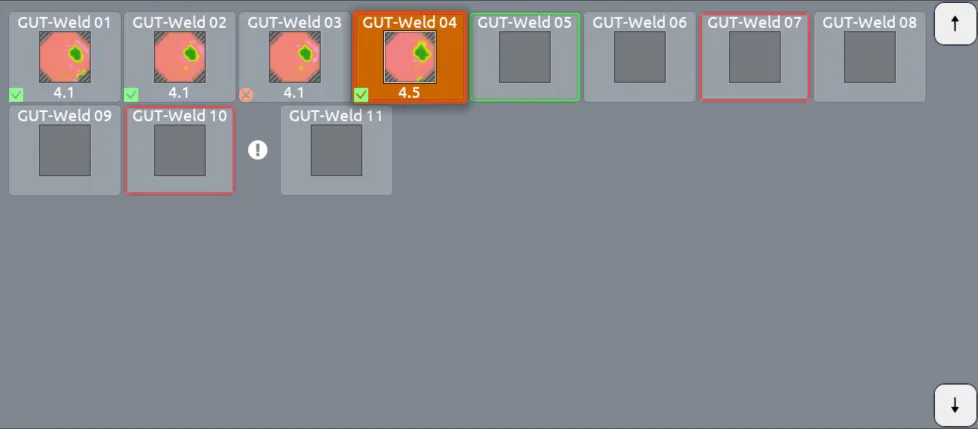
Grid View
Selecting Grid only displays the C-Scans, decision, category color, and measured diameters of each joint. This has the benefit of conserving space.
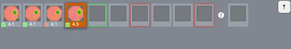
Stack changes are still displayed with the ! marker and can still be displayed.

Grid with Details
- 4.9.0 and Newer
- 4.8.0 and Older
Selecting Grid with Details changes the display to include the same details as Grid with the joint labels, as well as measured diameter, indentation and stack thicknesses. If the measurements are out of bounds (as per the specifications defined in Desktop Tools), it will be displayed as red.

For versions 4.8.0 and older, this option was called Grid with Captions. Selecting this view changes the display to include the same details as Grid with the joint labels.
Slots
Each slot refers to each measurement required for each joint. There are three cases:
- For 2T welds, only one slot is used for measuring the front plate.
- For 3T welds, two slots are available for measuring from the front side and the back side (respectively).
note
It is not required to use the second slot, as Array Explorer is capable of performing measurements for 3T welds in 3T Mode.
- For adhesive bonds, the bonds may be configured to use up to 10 slots to display several features of the joint.
